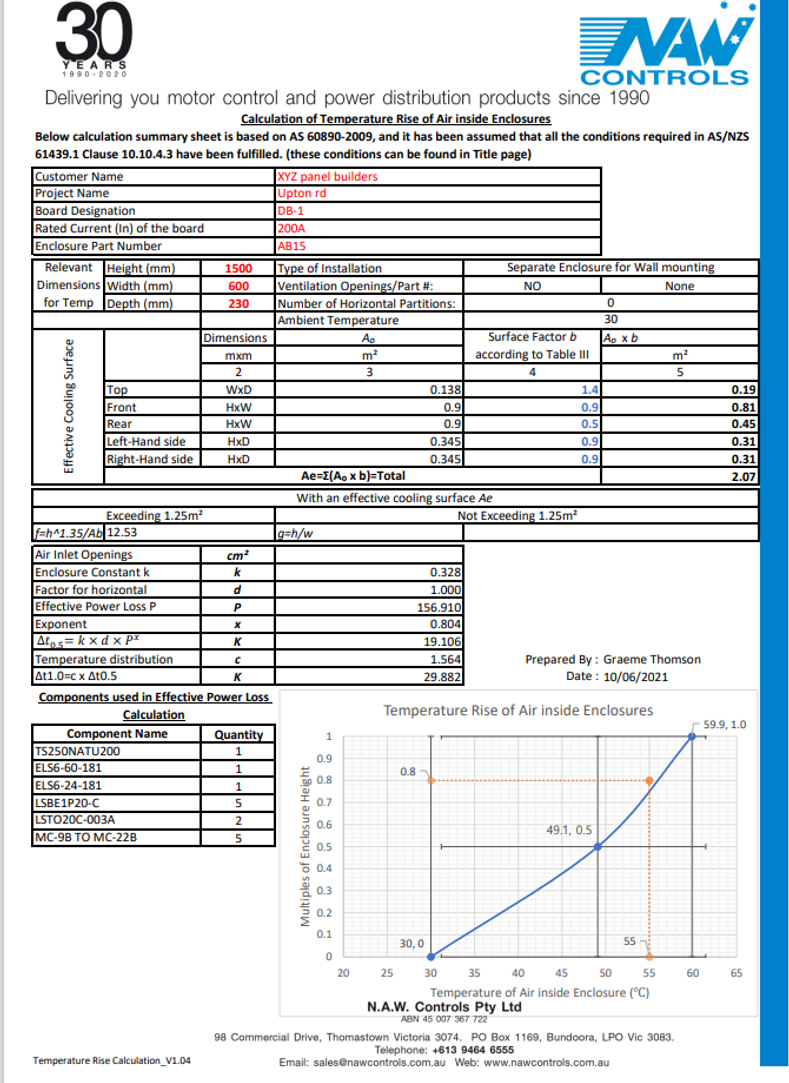
Did you know NAW Controls can now help with calculating the watts loss inside an enclosure based on the components selected?
As per AS/NZS 61439.1, Clause 10.10.4.3, an assembly with the rated current not exceeding 1600A can be verified by Calculation for the temperature rise of a single or multiple compartment assembly.
Our software package helps you to select an enclosure based on the following criteria -
- What is the watts loss of the products selected to be installed in the enclosure?
- What is the watts loss of chassis / busbars being mounted in the enclosure?
- What is the watts loss of cables being connected inside the enclosure?
- The ambient temperature is also taken into consideration
Once the total sum of the watts losses from the components / cables & busbars being mounted in the enclosure is calculated, an enclosure is selected from the NAW Controls enclosure product range.The addition of ventillation louvres can also be selected if required
Please contact our Engineering office to further discuss calculating the watts loss of your current projects
Refernce points for calculating heat rise inside an enclosure -
As per AS/NZS 61439.1 Clause 10.10.4.3 ASSEMBLY with rated current not exceeding 1600A can be Verified by Calculation for Temperature-Rise of a single or multiple compartment assembly with methods of IEC 60890.
Below calculation sheet is based on AS 60890-2009, and in order to apply this calculation all the following conditions need to be fulfilled:
a) the power loss data for all built-in components is available from the component manufacturer;
b) there is an approximately even distribution of power losses inside the enclosure;
c) the rated current of the circuits of the ASSEMBLY to be verified (see 10.10.1) shall not exceed 80 % of the rated conventional free air thermal current (Ith) if any, or the rated current (In) of the switching devices and electrical components included in the circuit. Circuit protection devices shall be selected to ensure adequate protection to outgoing circuits, e.g. thermal motor protection devices at the calculated temperature in the ASSEMBLY;
NOTE 1 There is no common characteristic for switching devices and electrical components that describes the value of current to be used here. For the purpose of verifying the temperature rise limits the value of current is used, which describes the maximum continuous operational current that can be carried without overheating. This is e.g. for contactors the rated operational current Ie AC1 and for circuit breakers the rated current In.
d) the mechanical parts and the installed equipment are so arranged that air circulation is not significantly impeded;
e) conductors carrying currents in excess of 200 A, and the adjacent structural parts are so arranged that eddy-current and hysteresis losses are minimised;
f) all conductors shall have a minimum cross-sectional area based on 125 % of the permitted current rating of the associated circuit. Selection of cables shall be in accordance with IEC 60364-5-52. Examples on how to adapt this standard for conditions inside an ASSEMBLY are given in Annex H. The cross-section of bars shall be as tested or as given in Annex N. Where the device manufacturer specifies a conductor with a larger cross-sectional area this shall be used;
g) for enclosures with natural ventilation, the cross-section of the air outlet openings is at least 1,1 times the cross section of the air inlet openings;
h) there are no more than three horizontal partitions in the ASSEMBLY or a section of an ASSEMBLY;
i) for enclosures with compartments and natural ventilation the cross section of the ventilating openings in each horizontal partition is at least 50 % of the horizontal cross section of the compartment.
NOTE: Option with Ventilation openings is only available for Enclosures with an Effective cooling surface (Ae) higher than 1.25m2 (defined as per AS 60890-2009).
A sample of the calculation based on components selected v's enclosure size required under AS/NZS 61439.1

